Introduction
In part I this article I demonstrated that some of the rules in regards to SMB Direct and the Hyper-V vSwitch as we know them for Windows Server 2012 R2 have changed with Windows Server 2016. We focused on the fact that you can expose RDMA to a vNIC exposed to the management OS created on a vSwitch. This means that while in Windows Server 2012 R2 you cannot expose RDMA capabilities via a vSwitch, even when you are using a non-teamed RDMA capable NIC, this is no longer true with Windows Server 2016.
While a demo with a vSwitch on a single NIC as we did in part I is nice it’s unlikely you’ll use this often if at all in the real world? Here we require redundancy and that means NIC teaming. To do so we normally use a vSwitch created on a native Windows NIC team. But a native NIC teaming does not expose RDMA capabilities. And as such a vSwitch created against a Windows native NIC team cannot leverage RDMA either. Which was the one of the reasons why a fully converged scenario in Windows Server 2012 R2 was too limited for many scenarios. Loss of RSS on the vNIC exposes to the management OS was another. The solution to this in Windows Server 2016 Hyper-V comes with Switch Embedded Teaming (SET). Now using SET in each and every situation might not be a good idea. It depends. But we do need to know how to configure it. So let’s dive in.
Switch Embedded Teaming (SET) exposes RDMA to the vSwitch
Switch Embedded Teaming (SET in Windows Server 2016 allows multiple identical (make, model, firmware, drivers to be supported) NICs to be used or “teamed” within the vSwitch itself. The important thing to note here this does not use windows NIC teaming or LBFO (Load Balancing and Fail Over).
SET is the future and is needed or use with the Network Controller and Software Defined Networking in Windows. SET can also be used without these technologies. While today it supports a good deal of the capabilities of native Windows NIC teaming it also lacks some of them. In general SET is meant for full or partial converged scenarios with 10GBps or better NICs, not 1Gbps networking in a (hyper)converged Hyper-V scenario.
Please see New Windows Server 2016 NIC and Switch Embedded Teaming User Guide for Download for more information as there is just too much to tell about it.
Setting it up
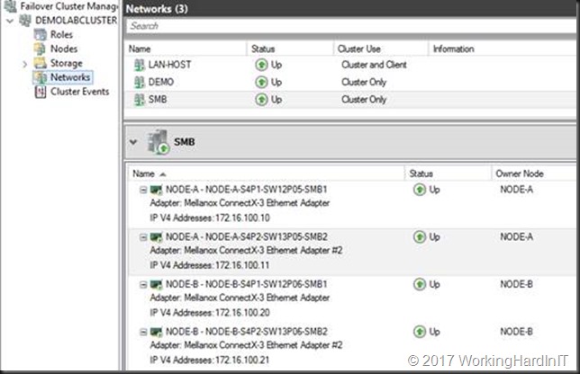
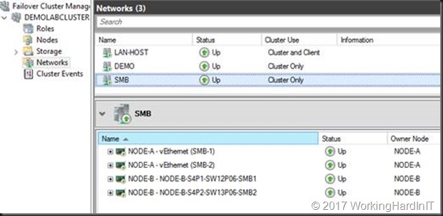
We start out with a 2-node cluster where each node has 2 RDMA NICs (Mellanox ConnectX-3) with RDMA enabled and DCB configured. Live migration of VMs between those nodes works over SMB Direct works. All NIC are on the same subnet 172.16.0.0/16 (thanks to Window Server 2016 Same Subnet Multichannel) and are on VLAN 110. In Failover Cluster Manager (FCM) that looks like below.
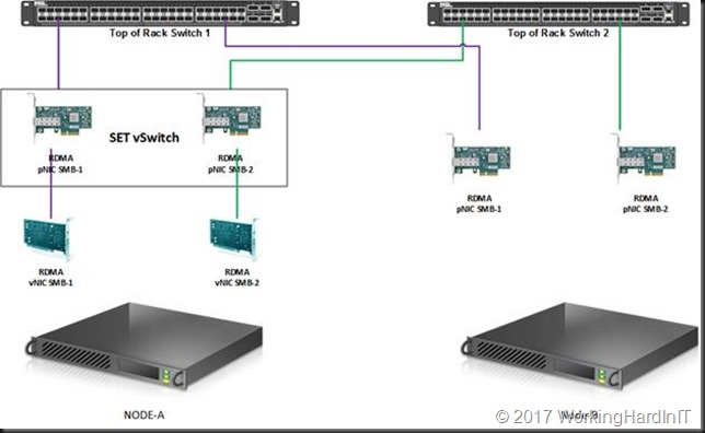
We’ll now use the rNICs to create a Switch Embedded Team.
#Create a vSwith
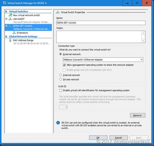
New-VMSwitch -Name RDMA-SET-vSwitch -NetAdapterName "NODE-A-S4P1-SW12P05-SMB1","NODE-A-S4P2-SW13P05-SMB2" -EnableEmbeddedTeaming $true

#This gives us a vSwitch in Hyper-V to use with the VMs this can be verified with PowerShell and in Hyper-V Manager.
Get-VMSwitchTeam -Name "RDMA-SET-vSwitch" | fl
Note that the teaming mode is switch independent, the only option supported with SET in Window Server 2016.
This also gives us a vNIC exposed to the management OS (default)
Get-VMNetworkAdapter -managementos
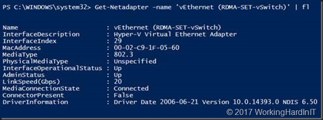
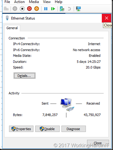
This is also visible as a vNIC in the mamagement OS called “vEthernet (RDMA-SET-vSwitch)”
Get-Netadapter -name "vEthernet (RDMA-SET-vSwitch)" | fl
This will be used to manage the host and to make its purpose clear we’ll rename it.
Rename-VMNetworkAdapter -ManagementOS -Name "RDMA-SET-vSwitch” -NewName “HOST-MGNT"
We’ll create 2 separate management OS vNICs for the RDMA traffic later. For now, we want the HOST-MGNT vNIC to have connectivity to the LAN and for that we need to tag it with VLAN 10.
Set-VMNetworkAdapterVlan -VMNetworkAdapterName "HOST-MGNT" -VlanId "10" -Access -ManagementOS

Get-VMNetworkAdapterVlan -ManagementOS -VMNetworkAdapterName "HOST-MGNT"
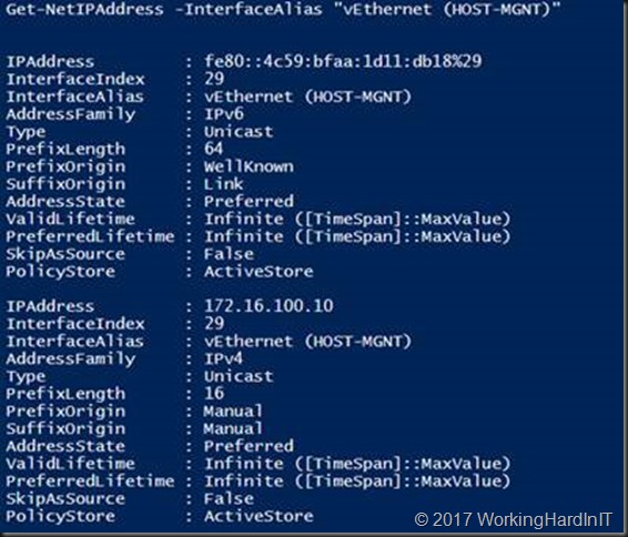
The vNIC actually “inherited” the IP configuration of one of our physical NICs and we need to change that to either DHCP or a correct LAN IP address and settings.
Get-NetIPAddress -InterfaceAlias "vEthernet (HOST-MGNT)"
You can use the code below to set the HOST-MGNT vNIC to DHCP
$IPVersion = "IPv4"
$NetAdapter = Get-NetAdapter -Name 'vEthernet (HOST-MGNT)' | ? {$_.Status -eq "up"}
$NetIPInterface = $NetAdapter  | Get-NetIPInterface -AddressFamily $IPVersion
If ($NetIPInterface.Dhcp -eq "Disabled")
{
# Clear the existing gateway or it may linger
If (($NetIPInterface | Get-NetIPConfiguration).Ipv4DefaultGateway)
{
$NetIPInterface | Remove-NetRoute -Confirm:$false
}
# Enable DHCP so IP address is obtained automaticaly
$NetIPInterface | Set-NetIPInterface -DHCP Enabled
# Make sure the DNS Servers are also obtained automatically
$NetIPInterface | Set-DnsClientServerAddress -ResetServerAddresses
}
To finalize the HOST-MGNT vNIC configuration we enable priority tagging on it. If we don’t we won’t see any traffic other than SMB Direct tagged at all!
# We set priority tagging on the Host vNIC or priority tagging will not work except SMB Direct traffic
Set-VMNetworkAdapter -ManagementOS -Name "HOST-MGNT" -IeeePriorityTag on

#Let's check our work
Get-VMNetworkAdapter -ManagementOS -Name "HOST-MGNT" | fl Name,IeeePriorityTag
Before we go any further we’ll remove the VLAN tag from the rNICS as we don’t want it interfering with egress traffic being tagged by them or ingress traffic being filtered because it doesn’t match the VLAN ID on the rNICs.
Set-NetAdapterAdvancedProperty -Name "NODE-A-S4P1-SW12P05-SMB1" -RegistryKeyword VlanID -RegistryValue "0"
Set-NetAdapterAdvancedProperty -Name "NODE-A-S4P2-SW13P05-SMB2" -RegistryKeyword VlanID -RegistryValue "0"
From here on we’ll focus on the RDMA capable vNICs well create and use for SMB traffic.
We create 2 vNIC on the management OS for SMB Direct traffic.
#Now add 2 host vNICs for the SMB Direct Traffic
#SMB Multichannel will take care or bandwidth aggregation and redundancy
Add-VMNetworkAdapter -SwitchName RDMA-SET-vSwitch -Name SMB-1 -ManagementOS
Add-VMNetworkAdapter -SwitchName RDMA-SET-vSwitch -Name SMB-2 -ManagementOS
#Take a peak at what we have now
Get-VMNetworkAdapter –ManagementOS
Now these vNIC need an IP address, this can be in the same subnet because we have Windows Server 2016 SMB multichannel.
New-NetIPAddress -InterfaceAlias "vEthernet (SMB-1)" -IPAddress 10.10.180.91 -PrefixLength 24 -Type Unicast
New-NetIPAddress -InterfaceAlias "vEthernet (SMB-2)" -IPAddress 10.10.190.91 -PrefixLength 24 -Type Unicast

#For good measure in my lab and for this use case I don’t need those vNICs registered in DNS
Get-NetAdapter -Name "vEthernet (SMB*)" | Set-DnsClient -RegisterThisConnectionsAddress:$false
We than also need to put the vNICs in the correct VLAN. Remember that DCB / PFC priority tagging needs tagged VLAN so carry that priority. Right now, we can see that these are untagged.
Get-VMNetworkAdapterVLAN -ManagementOS -VMNetworkAdapterName SMB*
So we tag them with VLAN ID 110
Set-VMNetworkAdapterVLAN -ManagementOS -VMNetworkAdapterName SMB-1 -Access -vlanid 110
Set-VMNetworkAdapterVLAN -ManagementOS -VMNetworkAdapterName SMB-2 -Access -vlanid 110

Get-VMNetworkAdapterVLAN -ManagementOS -VMNetworkAdapterName SMB*
We enable jumbo frames on the vNICs. Remember that the physical NICs in the SET have jumbo frames enabled as well.
Get-NetAdapter -Name "vEthernet (SMB-1)" | Set-NetAdapterAdvancedProperty -RegistryKey "*JumboPacket" -RegistryValue 9014
Get-NetAdapter -Name "vEthernet (SMB-2)" | Set-NetAdapterAdvancedProperty -RegistryKey "*JumboPacket" -RegistryValue 9014
#We can check this by running
Get-NetAdapter -Name "vEthernet (SMB-1)" | Get-NetAdapterAdvancedProperty -RegistryKey "*JumboPacket"
Get-NetAdapter -Name "vEthernet (SMB-2)" | Get-NetAdapterAdvancedProperty -RegistryKey "*JumboPacket"
Normally all traffic that is originated from vNICs gets any QOS values set to zero. There is one exception to this and that’s SMB Direct traffic. SMB Direct traffic gets tagged with its QoS priority and that is not reset to 0 as it bypasses the vSwitch completely. But if we set other priorities on other types of traffic for DCB PFC and or ETS that passes over these vNICs we must enable priority tagging on these NICs as well or they’ll be stripped away.
Set-VMNetworkAdapter -VMNetworkAdaptername SMB-1 -ManagementOS -IeeePriorityTag On
Set-VMNetworkAdapter -VMNetworkAdaptername SMB-2 -ManagementOS -IeeePriorityTag On

Get-VMNetworkAdapter -ManagementOS -Name "SMB*" | fl Name,SwitchName,IeeePriorityTag,Status
The association of the vNIC to pNICs is random. This also changes during creation and destruction (disabling NICs, restarting the OS). We can map a vNCI to a particular pNIC. This prevents suboptimal use of the available pNICs and provides for a well know predictable path of the traffic. We do this with the below PowerShell commands.
#Set the mappings
Set-VMNetworkAdapterTeamMapping -VMNetworkAdapterName SMB-1 -PhysicalNetAdapterName "NODE-A-S4P1-SW12P05-SMB1" -ManagementOS
Set-VMNetworkAdapterTeamMapping -VMNetworkAdapterName SMB-2 -PhysicalNetAdapterName "NODE-A-S4P2-SW13P05-SMB2" -ManagementOS
#Check the mappings
Get-VMNetworkAdapterTeamMapping -managementOS
Finally, last but not least, we should enable RDMA on our two vNICs or SMB Direct will not kick in at all.
#Enable RDMA on it
Enable-NetAdapterRDMA "vEthernet (SMB-1)", "vEthernet (SMB-2)"
Right now, we have it all configured correctly on one node of our 2-node cluster. The SMB network look like this now:
The cluster now looks like below.
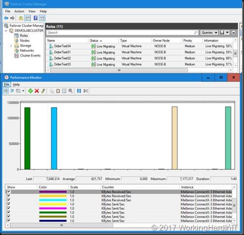
We can live migrate VMs over SMB Direct in this mixed scenario where one node has pNICs RDMA NICs, 1 node has SET with vNICs for RMDA.
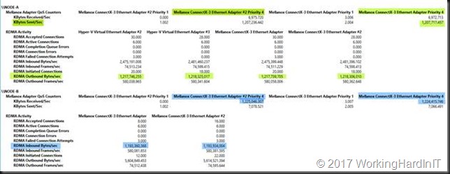
When looking at this in report mode we clearly see Node-A send SMB Direct traffic (tagged with priority 4, green) over its RDMA enabled SET vNICs to Node-B which still has a complete physical rNIC set up (blue).
As you can see in the screen shots above we now have RDMA / SMB Direct working with SET / RDMA vNICs on one node (Node-A) and pure physical RDMA NICs on the other (Node-B). This gives us bandwidth aggregation and redundancy. To complete the exercise, we configure SET on the other node as well. But it’s clear SET and RDAM will also work in a mixed environment.
We’ll discuss some details about certain aspects of the vNIC configuration in future articles. Things like the why and how of Set-VMNetworkAdapterTeamMapping and the use of -IeeePriorityTag. But for now, this is it. Go try it out! It’s the basis for anything you’ll do with SDNv2 in W2K16 and beyond.

