
I’ve been setting up a number of Hyper-V clusters with Mellanox ConnectX3 Pro dual port 10Gbps Ethernet cards. These Mellanox cards provide a nice amount of queues (128) for DVMQ and also give us RDMA/SMB Direct capabilities for CSV & live migration traffic.
Mixed Switches Environments
Now RoCE and DCB is a learning curve for all of us and not for the faint of heart. DCB configuration is non trivial, certainly not across multiple hops and different switches. Some say it’s to be avoided or can’t be done.
You can only get away with a single pair of (uniform) switches in smaller deployments. On top of that I’m seeing more and more different types of switches being used to optimize value, so it’s not just a lab exercise to do this. Combine this with the fact that DCB is an unavoidable technology in networking, unless it get’s replaced with something better and easier, and you might as well try and learn. So I did.
Well right now I’m successfully seeing RoCE traffic going across cluster nodes spread over different racks in different rows at excellent speeds. The core switches are DELL Force10 S4810 and the rack switches are PowerConnect 8132Fs. By borrowing an approach from spine/leave designs this setup delivers bandwidth where they need it a a price point they can afford. They don’t need more expensive switches for the rack or the core as these do support DCB and give the port count needed at the best price point. This isn’t supposed to be the top in non blocking network design. Nope but what’s available & affordable today in you hands is better than perfection tomorrow. On top of that this is a functional learning experience for all involved.
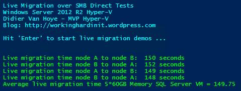
We see some pause frames being sent once in a while and this doesn’t impact speed that very much. It does guarantee lossless traffic which is what we need for RoCE. When we live migrate 300GB worth of memory across the nodes in the different racks we get great results. It varies a bit depending on the load the switches & switch ports are under but that’s to be expected.
Now tests have shown us that we can live migrate just as fast with non RDMA 10Gbps as we can with RDMA leveraging “only” Multichannel. So why even bother? The name of the game low latency and preserving CPU cycles for SQL Server or storage traffic over SMB3. Why? We can just buy more CPUs/Cores. Great, easy & fast right? But then with SQL licensing comes into play and it becomes very expensive. Also storage scenarios under heavy load are not where you want to drop packets.
Will this matter in your environment? Great question! It depends on your environment. Sometimes RDMA is needed/warranted, sometimes it isn’t. But the Mellanox cards are price competitive and why not test and learn right? That’s time well spent and prepares you for the future.
But what if it goes wrong … ah well if the nodes fail to connect over RDAM you still have Multichannel and if the DCB stuff turns out not to be what you need or can handle, turn it of and you’ll be good.
RoCE stuff to test: Routing
Some claim it can’t be done reliably. But hey they said that for non uniform switch environments too ![]() . So will it all fall apart and will we need to standardize on iWarp in the future? Maybe, but isn’t DCB the technology used for lossless, high performance environments (FCoE but also iSCSI) so why would not iWarp not need it. Sure it works without it quite well. So does iSCSI right, up to a point? I see these comments a lot more form virtualization admins that have a hard time doing DCB (I’m one so I do sympathize) than I see it from hard core network engineers. As I have RoCE cards and they have become routable now with the latest firmware and drivers I’d love to try and see if I can make RoCE v2 or Routable RoCE work over different types of switches but unless some one is going to sponsor the hardware I can’t even start doing that. Anyway, lossless is the name of the game whether it’s iWarp or RoCE. Who know what we’ll be doing in 5 years? 100Gbps iWarp & iSCSI both covered by DCB vNext while FC, FCoE, Infiniband & RoCE have fallen into oblivion? We’ll see.
. So will it all fall apart and will we need to standardize on iWarp in the future? Maybe, but isn’t DCB the technology used for lossless, high performance environments (FCoE but also iSCSI) so why would not iWarp not need it. Sure it works without it quite well. So does iSCSI right, up to a point? I see these comments a lot more form virtualization admins that have a hard time doing DCB (I’m one so I do sympathize) than I see it from hard core network engineers. As I have RoCE cards and they have become routable now with the latest firmware and drivers I’d love to try and see if I can make RoCE v2 or Routable RoCE work over different types of switches but unless some one is going to sponsor the hardware I can’t even start doing that. Anyway, lossless is the name of the game whether it’s iWarp or RoCE. Who know what we’ll be doing in 5 years? 100Gbps iWarp & iSCSI both covered by DCB vNext while FC, FCoE, Infiniband & RoCE have fallen into oblivion? We’ll see.


